Stepper motors are widely used in various types of control equipment such as CNC machine tools, medical instruments, instrumentation, etc. Its rotation is operated step by step at a fixed angle. Its main feature is that there is no accumulated error and 100% accurate control can be achieved. Therefore, it has a wide range of applications in various open-loop control systems. There are many types of control methods for stepper motors, including an integrated and integrated stand-alone controller, and a variety of control cards that are attached to the computer's expansion slot. However, for a small system with a microcomputer as the core, the microcomputer can be used directly. Existing port resources, especially parallel ports, enable stepper motor operation control. This kind of control method does not require additional hardware equipment, which saves equipment costs. Second, it does not occupy ISA or PCI expansion slots and saves computer resources. Third, it is flexible and easy to program. It is an ideal choice. 1 The basic control principle of the stepper motor The stepper motor is an actuator that converts electric pulses into angular displacements. Each input of a pulse signal turns the motor over a certain angle (some stepping motors can directly output line displacement, Called a linear motor). Because the reactive stepper motor has a high performance-cost ratio and is widely used, this paper mainly introduces the control principle and parallel port control method of the reactive stepper motor. Taking a single three-shot operation as an example, the basic structural principle of a stepper motor, such as the basic rotation principle of a stepper motor, is to energize the phase at the wrong tooth position, and the rotor will be under the action of the electromagnetic force to the magnetic permeability. The maximum (or least reluctance) position is rotated, that is, it tends to rotate toward the tooth. Let A phase first energize (B, C two phases are not energized), generate magnetic flux in the direction of AA axis, and form a closed loop through the rotor. At this time, the A and A poles become the N and S poles of the electromagnet. Under the action of the magnetic field, the rotor always tries to switch to the position where the reluctance is small, that is, to go to the position of the tooth aligning the teeth of the rotor A and A (a); then the B phase is energized (A and C are not energized for two phases. ), The rotor rotates 30 clockwise; then the C phase is energized (A, two phases are not energized), and its teeth are aligned with the C, C' poles (c). If energized in the order of A*..., the rotor of the motor rotates counterclockwise. The rotation of the stepping motor, that is, the A-phase, B-phase, and C-phase control windings are energized in a specific order, requires a matching driving circuit (as shown), and the circuit is controlled by the input electric pulse. This kind of electric pulse can be a switch quantity, can also be the digital quantity, in our small-scale computer control system, this digital quantity is given by the computer parallel mouth. A control electric pulse is output from the parallel port, and the stepping motor goes one step, ie, rotates through a / step angle, until it reaches the corresponding design angle according to the control request. Therefore, the stepping motor and its driving circuit are interconnected. As a whole, the running performance of the stepping motor is a comprehensive effect formed by the combination of the motor and the drive circuit. The angle of rotation is controlled by the number of externally input electric pulses, which is the basic control principle of the stepping motor. 2 Parallel port definition and setting The parallel port is a standard interface for general microcomputers. It has 25 cores and can simultaneously transmit information through 8 data lines, one byte at a time. It is usually used for printers and plotters that require eight data transmissions. Multiple peripherals. Through the parallel port can be data output, data input can also be made, very suitable for general digital I / O. Because the stepper motor has a very high transition accuracy, more work in the open-loop control state, so you can use the parallel port data output The function replaces the pulse signal generator in the traditional stepper motor control circuit. A digital pulse sequence is generated by the program control parallel port and sent to the drive circuit of the stepper motor as an electrical pulse signal to control the rotation of the stepping motor. The bit (B1/B3/B5) is used for the motor's steering control. The zero-value motor rotates clockwise. When it is set to 1, it rotates counterclockwise; the low position (B0/B2/B4) is used to provide stepping drive pulses to the motor. The data bits generate a continuous sequence of 1 and alternately exchanged digits at a certain delay interval. Therefore, the control word controlling the clockwise rotation of three stepper motors is: 0X15(1)/0X00(0); the control word of three motors rotating counterclockwise at the same time is: 0X3F(1)/0X2A (the principle block diagram is as follows Note: The pulse direction of the motor parallel port control system is set by the computer system setup program. The port setting of the motor parallel port is automatically configured by the computer system setup program. The initialization process configures the parallel port as LPT1 (for a general-purpose microcomputer equipped with a parallel port). Corresponding interrupt resources and different data addresses, status addresses and control addresses: IRQ7, data address 0378H, status address 0379H, control address 037AH, and the pin assignment of the parallel port are shown in Table 1. Table 1 Parallel Port Pin Assignment Pin Identifier Data Bit Port Pin Identifier Data Bit Port Pin Identifier Data Bit 3 Stepper Motor Parallel Port Control Method 3.1 Control System Schematic The stepper motor control system discussed in this paper is designed by the author. The subsystem of an industrial control project, the design requirements of the subsystem are: control the three stepper motors with the parallel port of the microcomputer, and simultaneously complete -45+45, -90\+9 (1 angle rotation. The design adopts The data port of the parallel port, namely 0378H as the entry address, allocates 3 pairs of data bits for motor control to 3 stepper motors. They are: motor A distribution B1/B0, motor B distribution 3.2 control program design method and flow According to the characteristics of the stepper motor, when the parallel port is used to control the motor, the following problems need to be solved: The stepping drive pulse must have a certain width, and the miniature stepping motor of the American company SHAPHON is used in the project. The motor adopts a negative pulse working mode, which has a certain degree of requirement on the uniformity of the driving pulse, and at the same time, the pulse width is not less than 5LS. Therefore, in the process of program design, it is used. The delay method allows the BO/B2/B4 output negative pulse width and uniformity to reach the motor requirements. The directional control pulse of the motor has special requirements, that is, when the motor changes direction, it must be performed after the motor decelerates to stop. For this reason, during programming, the directional control signal for each commutation precedes the stepper drive signal, so that the commutation signal can be guaranteed to be the first pulse in the next direction after the last pulse in the previous direction is over. Issued before arrival. Stepper motor control lift speed curve design. Due to the existence of the time constant and the inertial effect, the stepper motor must have a speed-up and speed-down process from start to stop. The design of the speed-up and speed-down is very important. If it is not designed properly, it will cause the stepping motor to stall. Out-of-step, slow downspeed and other issues. The speed increase process consists of kick frequency plus speed curve. The speed reduction process is the opposite. The ideal speed curve should be an exponential curve. However, according to the characteristics of the motor and the actual engineering test, this system adopts the method of subsection straight line approximation. , and when the motor rises to the highest frequency, design a constant-speed section that maintains high-speed operation to increase the motor speed. Acceleration and deceleration control curves are as shown, Fq is the starting frequency. Addition and deceleration control curve (4) program execution flow. The control program uses LabWIndows/CVI language and has a simple and convenient program interface. -45\+ 45\-90\+90)Angle control, corresponding to the four button controls, and with the interface exit button, just click the relevant button to complete all operations, so that the stepper motor control is crisp, Intuitive. The program design for each rotation angle is completely common. The main flow includes: Open the operation interface. Determine if this button is selected. If selected, read in the port address. Assign the initial kick frequency to the frequency up section, Accelerate control, Constant speed, Keep the down section, Deceleration control, Stop after the port. Clear to return to the operation interface. The entire control program has passed the engineering test and practical application, and the operation effect is good. It is believed that the secondary development and application of computer parallel port resources can play a certain role in reference. 4 main test procedures
Strips/Corrugated Texture Pu Sandwich Panels
Rich selection of textures and colors meet different decoration requirements, giving the city and the buildings a new look. Strips/Corrugated Texture PU Sandwich Panels External Wall Panels,Insulated Outdoor Wall Panels,Strips Texture Pu Sandwich Panels,Corrugated Texture Pu Sandwich Panels Jinan Zhengtang Insulation Decoration Material Co.Ltd , https://www.ztwallsiding.com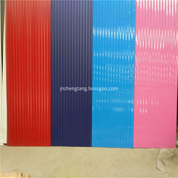
The PU foam is the most advanced and eco-friendly insulation material in the world. With the help of the back aluminum foil, the thermal preservation effect achieves the best.
The unique structure prevents the heat loss in winter. Meanwhile it reduces the heat of the summer sunshine.
Aceta paintcoat and flurocarbon paint of weather resistance performance are applied on surface of wall panel. It is reserved with superior self-cleaning, weather resistance, corrosion resistance and acid& alkali resistance performance.
Light weight with 3.7Kgs/m2 makes the installation easy.
The installation process is clean and tidy without any noise and dust, construction waste.
Different selections of accessories meet different effects.
High quality and stable performance: Manufactured in CNC automation production line, the product pass rate can reach 99.9% with stable chemical structure and physical structure.